Lab37 Internship
I just wrapped up my last week at Lab37, a kitchen robotics company in Pittsburgh, PA. I want to open with a huge thank you to everyone at Lab37, including Dan Tascione, Juilie Derence, Jason McMullan, Sean Hyde, and Eric Meyhofer, for allowing me to work on their software team this summer. I also wanted to thank them for allowing me to write this blog post about my experience and share it with you all. This post is going to highlight some of my favorite projects and fun anecdotes from my time at Lab37.
What I Worked On
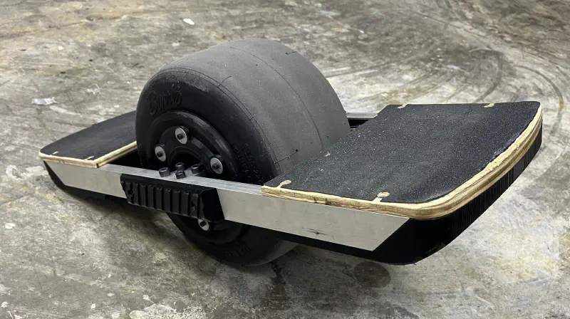
At a high level, I was working on Lab37’s bowl-building robot: CHAD. This robot is designed to be the equivalent of a line cook in a fast food restaurant (think Chipotle and similar). The robot dispenses empty cardboard bowls onto a conveyor belt, dispensing the correct amount of ingredients at each station. At the end, each bowl has a lid placed on it, is placed into a bag, and then the bag is pushed out to the end of the robot. You can see a short promotional video of the robot below.
The First Week
I wasn’t sure what to expect when I came to my first day. You don’t see many “Day in Life of ___ Intern” videos on YouTube about interns working at small companies. I had gotten a tour of the office when I came and interviewed, and I got to meet many of my coworkers but, I had very little idea of what exactly I would work on.
After I arrived and got all of my accounts set up, I was tasked with adding some diagnostic information to a page on the robot’s VueJS control interface. One small problem: I had zero VueJS experience, nor any experience with ARK, the robotics toolkit used in-house. This was a “trial by fire” moment that I wasn’t expecting. I spent the next 3 hours Ctrl-Clicking through VSCode, determining where I needed to pull data from in the pipeline. After 4 hours, I had my first pull request!
Over the next few days, I worked through the team’s list of UI tweaks and bugs that had been sitting in the “Todo” pile for quite a while. The software team was only 5 people, 2 of which were interns (Anna Lee and I), so there was no luxury of burning a day to work off tech debt on the front end. Surprisingly, the UI experience gave me a ton of insight into how the robot’s pipeline worked. Most of the changes I was making were surfacing data to the front end. The hardest part was finding where each of the data points was and finding what channels (similar to ROS topics) they were published on. Going through and tracing all of the data brought me through multiple systems on the robot.
The Modern C++ Shock
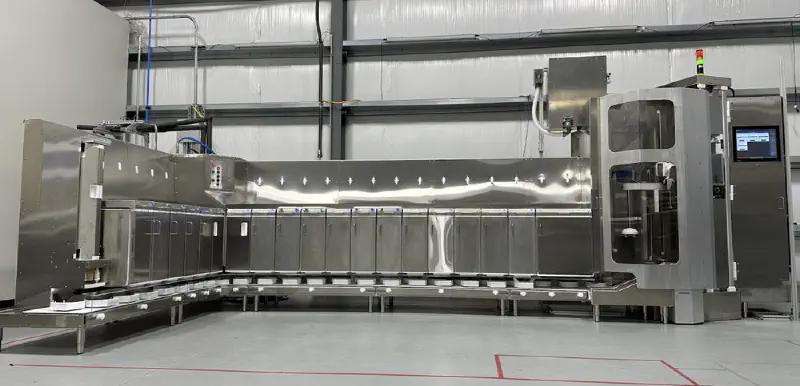
My first task on the actual pipeline of the robot was implementing Turbo Mode. Turbo Mode was a mode where the lidder and the bagger were overridden so that a human could lid and bag the bowls. This was needed since bagging and lidding were the 2 main bottlenecks for speed on the first-generation robot. We had a robot that was running in production (seen here) that was fulfilling orders. During peak hours of lunch and dinner, the robot was unable to keep up with the incoming orders because of the lidder and bagger. Turbo mode was required while the team worked on an improved v2 version of those components. The current solution to put the robot into turbo mode was about 8 steps that had to be manually put in by a human. My task was to implement a single button to take the robot into and out of turbo mode.
My first iteration of the design was sending all of the steps from the front end as if the user was “tapping” on each of them. This was a workable solution, but we now wanted to add an audible alert to let the kitchen staff know that the robot was falling behind. This meant we had to know the state of turbo mode on the robot. Due to technical limitations, it was now required to convert the “web turbo mode” to a C++ stage in the robot’s pipeline. I had put on my resume that I had some basic C++ experience with Arduino through multiple projects including Photoframe and Hoverwheel. Little did I know that Arduino C++ is a way different than modern C++.
Due to how big the codebase had grown to this point (Surprise! There’s a lot of code to put food in bowls reliably!), there was a ton of abstraction and compiler
optimizations. This was quite confusing coming from Arduino land where you have 2 functions: setup() and loop(). It probably took me close to 3 hours just to
get a stage to print “Hello World”. This wasn’t due to the codebase being bad or anything (I can get a stage running in about 5 minutes now!), it was the lack of
familiarity with the tools. Most of the ways I learn new frameworks is through Googling and looking at examples. For this, however, I had an entire codebase of examples but there was not much to Google for specific questions. This was mainly due to ARK being a licensed tool and not having widespread adoption to a point where you can find answers to dumb questions on
Stack Overflow. This marked a huge shift in how I started to learn the framework and tools the team used.
I could no longer just find what I wanted to build online and then modify it to suit my needs, it was now going into super complex examples and finding the different elements to get an MVP. This experience forced me to strengthen my reverse engineering and tracing skills. I also learned that C++ has gained an immense amount of baggage in its 40+ years. It was eye-opening to see how languages like Swift brought the speed of compiled languages and the standard library and syntax of languages like TypeScript and Python to make something that is simple, efficient to write, and extensible. I am even more curious to try languages like Go and Rust since they follow a similar path as Swift.
Lessons in Human Interaction
I was tasked with adding “Playbooks” to the robot’s control interface to help inform staff about steps to resolve issues. Lab37 revolves around the idea of Playbooks. Instead of having the idea of “we will just write docs as we go along”, they actively encourage every department to write out step-by-step guides for how to resolve issues, complete tasks, and other topics. For the software team, we actively use GitHub Wikis to manage our set of playbooks specific to the software. The kitchen staff who operate the robot on a day-to-day basis have their own set of playbooks for kitchen tasks and operating the robot.
The requirements were to:
- Surface the correct playbook to the user when faults come up on the screen.
- Display the playbook on the robot with a single tap
- Allow people not on the software team to modify and create playbooks in an intuitive format
The business and kitchen ops teams utilize Notion for most of their documentation and Playbooks. Fortunately, Notion has an excellent API that can be used to gather all of the information about a page. There are great JS libraries for rendering Notion to Markdown documents and then rendering Markdown inside of Vue. To keep all secrets safe, the robot makes all of its requests to a “Bridge” service on a VPS that acts as a proxy. All of the robots authenticate with it and then send any requests they have for cloud data through it. This poses some issues since the notion Markdown conversion library expects to call the Notion API without the “bridge”. This would be trivial to request data ourselves, and then only use the actual “rendering” function inside of the library but, Notion has one fatal flaw in its page retrieval endpoints.
When you go to request a page, you send the id of the page to notion and they return the top-level page data. If anything is indented, bulleted, numerically listed, or an image, you MUST make another call for EACH of those elements with their “block ID” to get their information. The notion Markdown rendering library recursively calls the API until it reaches the bottom level of each part of the page. Instead of rewriting the entire data fetching code (that was very complex and would likely have many bugs), I utilized the fact that JS does not care about types and will accept any JS class or object as the “client” when passed to the Markdown library (looking back I should have used Proxies). I wrote a mock Notion Client that used the same interface as the real Notion Client but translated all requests to the bridge communication protocol. I utilized JS promises to resolve each async function call as I received data back (bridge requests were made on one channel and then received on another channel once completed). Sure enough, the Notion to MD library accepted the fake notion client as the real thing and happily rendered out the page.
The biggest lesson I learned at Lab37 was the importance of keeping every user-facing feature as intuitive and simple as possible. The kitchen staff who operate the robot are not constantly watching the robot as it is working and often come up to the robot to fix issues. They did not watch it happen nor did they design the robot and know how to fix it. I did a ton of work to improve the verbosity of faults. Mainly, I made changes to tell the operator what they need to do (playbooks and simple resolution messages) and not what happened (that is saved in logging for engineering to determine the root cause). The kitchen staff does not care what happened to the robot, they care about what they need to do (next steps) to get the robot fixed and allow them to get back to their other tasks. When the operator goes to clear a fault, instead of the menu showing things like “Retry”, “Clear without Retry” and “Operator Resolved”, I changed it to be station specific with the operator choosing from 1-3 “Resolution Actions” that specifically told the operator “here are the 3 ways to fix this”. TL;DR: If something is wrong, tell the user what you need them to do instead of telling them what is wrong. They didn’t design the robot and are not expected to know what to do if you tell them what is wrong.
ZPL My Beloved
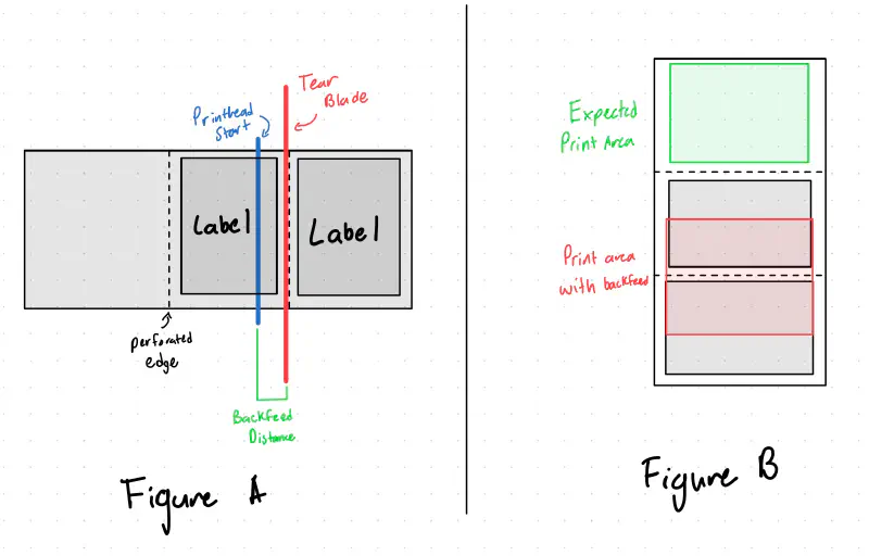
Another project I got to work on was new labels for the aforementioned Bagger V2. The mechanism for applying a label to a bag tensions the label paper to allow a label to automatically peel itself when labeled. One problem: Zebra printers have a function called a “back feed”. Backfeeds allow the printer to print a label to a point where it is easily tearable with the printer’s blade. However, when you do that, the next label is already past the print head (see Figure A). Therefore a “backfeed” is required to bring the next label back to the start of the printhead to print the entire label. The problem lies with the fact that if you are constantly pulling on the label paper to tension it, the printer does not have enough strength or grip to pull the label tape back in. This causes a dreaded double print where the printer gets confused about where a label starts and ends. This causes it to print one “label” across 2 physical labels (see Figure B). This was mainly caused by the IR label detector in the Zebra getting confused and starting the print at the wrong time
I solved this by first digging into the docs of ZPL, Zebra’s proprietary print protocol
to find that sending the ~JSO command
to the printer would allow it to disable back feed at the expense of about 1/4" of print distance at the bottom of the label. This was fine since we
were planning on redesigning the label anyway. The double print was catastrophic to the operation of the labeler and thus we wanted
to detect a double print before we made any movements that would jam it. Fortunately, Zebra printers have an odometry value stored
in the print head that is queryable. It appears to be linked to the encoder in the printer instead of being incremented in software.
This allows us to check the delta in print distance after a print. If it is >10cm, we know a double print happened and can stop
execution and alert the operator. Although it would be very unlikely that the printer would double print with the backfeed
disable command, if for some reason the transmission of commands got corrupted or there was a software bug that removed that command,
we can detect it before we jam the labeler to a point where it takes multiple minutes to resolve the jam.
In addition, I added a “preflight” check to the Zebra printer to prevent further execution if the printer had any active errors. It also un-pauses the printer if it is paused (usually after a label roll refill) in case the user forgot to hit the un-pause button.
ESXi Migration
One area of IT that I haven’t messed a ton with is Virtual Machines. My homelab runs everything on Docker mainly because of my limited
hardware resources. Fortunately, I was able to learn a ton about the migration and configuration of Proxmox by helping with the migration of local IT infrastructure
from VMWare ESXi to Proxmox. Originally, we were planning on just setting up an additional ESXi node to have a backup machine in case the production
server failed. This server was critical since it hosted the Solidworks EPDM databases and losing that for a week would cause major disruption.
Well ever since Broadcom acquired VWare,
they have made it prohibitively hard to find an installer image for ESXi. We decided to switch to Proxmox seeing as it has grown in popularity ever since
the VMWare acquisition and it recently added support for ESXi migration over the network. This proved to be quite simple for all of the VMs to be
transferred to Proxmox in under 15 minutes for most of the smaller VMs. There were only minor issues with network interfaces changing and the
netplan that the Ubuntu installer makes. I set up template VM images for Ubuntu to bootstrap VMs in the future.
We also experienced issues with how Proxmox and ESXi manage VLAN tagging. In ESXi, you make a specific virtual interface for every VLAN you would like to attach to.
You then add each VLAN interface you want into each VM. With Proxmox, it expects you to mark a physical interface as VLAN aware. You then create interfaces on each VM,
attached to the main physical interface, and then specify the VLAN for that VM interface. It also expects you to define the subnet and gateway for each VLAN you want to use
with the interface_name.vlan_id format described here. Overall, this gave me a ton of insight
into how VLANs worked since I don’t have any Layer 3 switching hardware at home.
“Hey Robot, I fixed the lidder.”
My last big project at Lab37 was implementing a voice assistant for the robot. The kitchen staff wanted some way of giving voice commands to the robot (surprisingly, they have become very attached to the robot and often ask it questions like it’s a coworker). I had known about Home Assistant’s Year of the Voice initiative they started (and are continuing) last year. This brought multiple open-source projects to build out a voice pipeline. Now, I didn’t want to run Home Assistant on the robot just to get a voice pipeline so I took a look at Rhasspy, the project that Home Assistant is based on. This application was surprisingly modular. For every step of the pipeline, it came with configurations for a few select options for that step as well as the ability to punch out to an HTTP service or use the MQTT protocol for completing the step. The hardest part about the voice pipeline was the intent processing. Originally I had assumed Rhasspy was using some NLP tools to match intent examples. Nope, it is just using Levenshtein distance through Fuzzywuzzy.
The actual audio processing pipeline consists of 2 steps: Wake word detection and transcription.
Wake Word
Wake word detection is a model that detects the use of a “wake word” such as “Alexa” or “Hey Google”. OpenWakeWord was a great fit since it was simple, provided training notebooks, and had a C++ fork that used the ONNX framework and ARK has support for running these models on the robot. Thus, we could keep all of the wake word detection on the robot without having to stream data out to a processing server.
We wanted to have our own wake words such as “Hey CHAD” or “Hey Robot”. Unfortunately, the training notebooks provided by OpenWakeWord produced a model that only worked 50% of the time. The running theory is that the TTS used to generate the training data was too quick in speaking (often combining the phrase “Hey Chad” into more of a “heyshad” sound), causing you to have to say the wake word at a faster than normal speed to have it trigger. We decided to just use the pre-built “Alexa” wake word model, with hopes of training a better custom wake word model in the future.
Transcription and Intent Processing
Transcription inside of Rhasspy was lackluster. Even on perfectly clean audio from me sitting at my desk in the quiet office, it was often making mistakes. A spoken phrase of “Hey robot, I fixed the lidder” produced transcriptions of “Hey rabbit, I minced the rabbi”. Surprisingly the fuzzy string searching got the intent correct, but that accuracy broke down once we started adding more intents. I had used Whisper for transcription of videos in the past, mainly because the models could be run locally on Apple Silicon at a decent rate (often 2-6x real time). We did not have any neural/tensor hardware acceleration on the robot and, that caused inference times on the robot to be around 1-2x speed. This sounds fine but on 3 seconds of audio, it was often a 2-4 second inference time before it produced a transcription (there are more steps than just inference: loading the large 2-6 GB model to memory, loading the audio, inference, and cleanup). Fortunately, Whisper has been wrapped into an API from OpenAI for a reasonable price (at the time of writing) of $0.006/minute of audio transcription. Since all invocations are ~3 seconds, this is very economical. We already used the OpenAI API on the robot for NoteAI (check out fellow intern Anna Lee’s writeup about her improvements to NoteAI here), and adding the Whisper endpoint was trivial.
Whisper handled the transcriptions perfectly. A nice feature was giving Whisper context to the situation including vocabulary specific to the robot. I provided context about the uncommon station names (Lidder, bagger, etc). This improved the transcriptions dramatically. For example, “Bowl Lidder” was transcribed as “Bowl Litter” but with context the transcript was correct. Whisper also handled transcription well in the noisy kitchen environment where most of the low end was all noise and a microphone frequency cutoff at 6khz. The transcriptions were correct with some minor errors that are handled by the fuzzy string searching.
Intent Processing
Intent processing as I have mentioned previously was handled with fuzzy string searching. The phrases to match against are generated from a YAML config file like below. I use a similar concept of “slots” from Rhasspy to reduce the amount of repeated intent definitions. When the intent stage loads, it generates all possible phrases from the config file. These phrases include the string to match against, the “target” of the intent, and the intent type. I would have liked to implement the forced-alignment technique discussed by NVIDIA but there was much more complexity than what was needed. We have about 160 possible intents on the robot and the fuzzy string searching seems to work well for that size.
  #
  # Example intent configuration
  # Comma-separated slots allow for synonyms of the first element
  # "<>" tags will be replaced with the slot value
  #

  slots:
    station_slots: &station_slots
      - "Bowl Lidder, lidder"
      - "Bowl Dispenser, bowler"
      - "Bagger"
      - "Conveyor, line"

  intents:
    - name: "Retry"
      sentences:
        - "Try <> again"
        - "Try again on <>"
        - "Do the <> again"
        - "Can you fix the <>"
        - "Retry <>"
      slots:
        *station_slots
      response: "Ok, I will retry the <>."
When a string is recognized, the phrase is forwarded to a tree system that attempts to infer the target if the intent does not have one assigned (such as saying “I fixed the error”, we don’t know what station they fixed). This inference logic looks different for each intent and eventually produces a station ID as the target. If the user specifies a target, the target string is converted into an assembly line station ID that we can then act upon. Based on the target and intent, we send the required commands to the rest of the pipeline for the intent and respond to the user with what action we completed.
When we asked the kitchen staff what they would like to use the voice assistant for, we were surprised that they would also like to ask about its current state such as
- “How many orders do you have?”
- “What ingredients are low?”
- “Do we need any more sauces?”
This was a simple system to implement by running similar checks that the alert system takes to determine if we need ingredients or sauces refilled. The robot responds, using OpenAI’s TTS service we also already used to read out alerts on a speaker in the kitchen, with what the kitchen staff needs to refill (remember back to my previous point of telling the kitchen staff their next action). If there is nothing to refill, it simply says “No stations need refilling at this time”.
Unfortunately, my internship ended before I got to see the voice assistant in action at the test kitchen. However, internal testing on our test robot was very promising. I hope to return for a short period this winter and see it in action!
Mixpanel Tracking
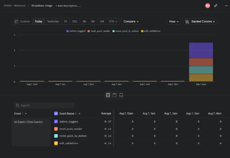
During my last week, I completed a small side project of adding Mixpanel event tracking to the control interface. Both the software team and business team had questions about what the kitchen staff was using on the touchscreen (mainly “Do they use that button and can we remove it?”). This was super relevant since I had just opened an issue on Maroon Rides to add usage tracking to our app. Mixpanel in Vue is super simple to add and I had tracking of most UI elements in under 2 hours. We now have fancy dashboards about how the kitchen staff is using the UI and, we hope this will drive our frontend feature development to a more simple and user-friendly UI. I’m hoping to add this to Maroon Rides sometime this semester because our team also has similar questions.
Summary
If you would like to order some food from CHAD, you can! Check out The Hungry Group and order something from The Hungry Cowgirl and The Hungry Siren.
I have learned so much in my time at Lab37. I learned how the software development process works on a small team. I learned how nice tests and simulators were to test features at your desk. I saw how developing a system to allow you to send repeatable commands expedites the bug-fixing and feature development process. I learned some advanced networking as well as non-software skills like using a lathe and laser welding (Thanks Nick!). I learned that it is really hard to make a robot open a paper bag. Most importantly, I learned that having a team where you can trust each person makes a huge impact on your productivity. The people at Lab37 are extremely talented and I am so grateful to learn from them this summer. I hope to be back and work with them more in the future.
Thank you everyone at Lab37 for making this one of the best summers ever,
- Brandon