Hoverwheel V1
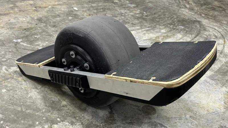
I have always wanted an Onewheel. There is something so satisfying about the movement mechanics that it just makes me marvel at it every time I see one. It’s great up until the point you go and attempt to purchase one. At the time of writing, the Onewheel Pint is $1,050… way out of my broke college student budget. The used market is not much better, with used boards going from $800-$1000 depending on how much use the board got.
Let’s go take a look at the DIY scene. There is VESC which is the leading PEV ESC on the market right now. Multiple companies are producing retrofit kits for Onewheels to break free from the grasp of Future Motion. These kits are about $300 by themselves and require you to already have an Onewheel. While I would love to play the eBay lottery of finding a cheap used Onewheel that had a broken controller but a perfectly working motor and battery system, it would still be way outside of my budget.
While researching, I stumbled upon a video from thedirits showing his $250 Onewheel that was built from the electronics of a used hoverboard.
This combination of electronics would only cost me around $50 to get and came with essentially everything I needed electronics-wise to build the board. Thedirits threw out the idea of using a single high-power hub motor. Instead, he used 2 smaller motors and bolted them together to effectively create a 500w motor for less than $50. This is genius.
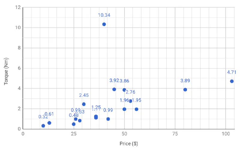
Hoverboard motors have dropped in price significantly due to the Hoverboard craze and China jumping on the bandwagon. Hoverboard motors have an insane torque/$ as seen in the data collected by ODrive. This is even assuming that the motors cost $40 each!
I started deal hunting and found that there were zero hoverboards on Facebook Marketplace that were within walking distance (remember that hoverboards are usually 25-30lbs) or under the magical $50 mark. I went on eBay and found a listing that included everything from a hoverboard except the outer casing and bulky metal frame. Perfect. I didn’t need any of those parts other than the axle brackets that I needed to cut out of the chassis. I purchased it for $75 which was about the same as the ones on Facebook Marketplace.
I set the constraints for the project as follows:
- $400 budget
- At least 4 miles of range
- About 8-12 mph at less than 80% duty cycle (more on this later)
- Less than 25lbs and handle to carry
Design and Assembly
I was tempted to use all of the models that thedirits provided, but watching the assembly video, there were multiple places that could be improved for a more finished look and easier assembly.
Frame
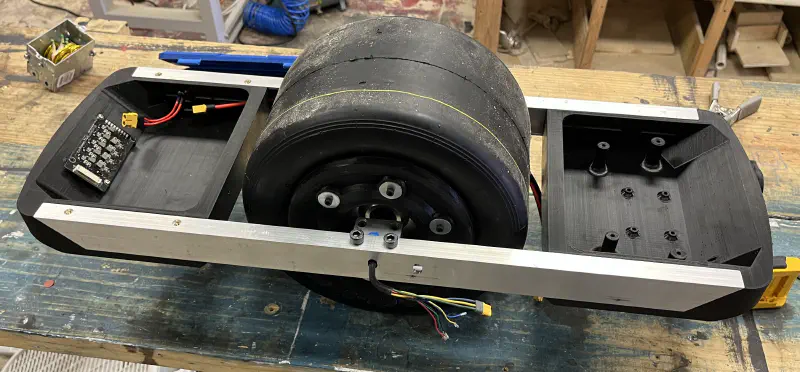
This board was designed very similarly to thedirits. The frame is made of aluminum U-Channel and 2 3D-printed compartments that slot into the channel. Each of these compartments is ~450g of plastic and takes ~20hrs on a Prusa MK3s on speed settings, 0.3mm layer height, and 20% infill. Everything is screwed together with M5 button head bolts and heat-set inserts. They are designed in a way that once they are unscrewed, they can be completely pulled out without removing any buttons or connectors from the aluminum rails.
There are holes in the corners of the compartments for wires to pass through. There is no easy way to waterproof these. I figured since I didn’t have a fender, I wouldn’t be riding it in wet conditions anyway.
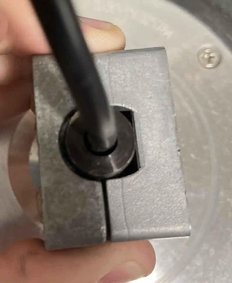
The motor mounts with 2 aluminum blocks that fit around the D-shaped shaft and clamp the motor shafts to the rail. Then 4 M8 bolts thread into the blocks to clamp everything down. These came from the original hoverboard as well (as well as a second donor) and required a bit of millwork to fit together properly. I also filed the small flange at the end of the shaft to make the whole shaft a uniform D-shape.
Hub Motor
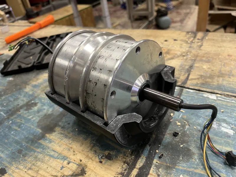
Thedirits was kind enough to release the exact model he used to make the 6" hub motor and a useful assembly video. My initial construction of the hub was difficult as the tolerances in the prints were too tight. Later I found that multiple other builders experienced the same issues. I reprinted the hub after I made multiple changes to the design. This was easily done by importing the .STL files into Fusion 360 and using the Prismatic Conversion tool (I highly recommend checking this out if you have an Educational or paid license!). I needed to offset the notch widths and diameter by about 1mm. The new files are available on the project’s GitHub.
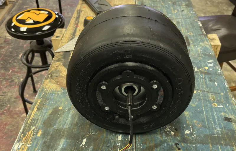
I used a Unilli 11x6x6 Go-Kart Tire that was about $30. This was an identical tire to what is found on an Onewheel XR. I used an 11x6x6 tire tube that fit well and a valve stem extension that was too long in hindsight. I used M4x40mm bolts and M4 fender washers to hold the entire wheel together. The fender washers are critical in preventing the bolts from pulling through the plastic bead locks.
All 3D printed parts for the hub motor were printed with PETG with 4 perimeters and 30% grid infill. They were printed on an Ender 3 at my local maker space, Starforge Foundry.
Electronics
All electronics in this version (except the battery system) were from the original hoverboard. The cost savings by doing this were immense and helped keep the total cost of the project under $400. The hardware is very cheap to replace if it does break since it has been commoditized and is available at nearly every major online retailer.
ESC
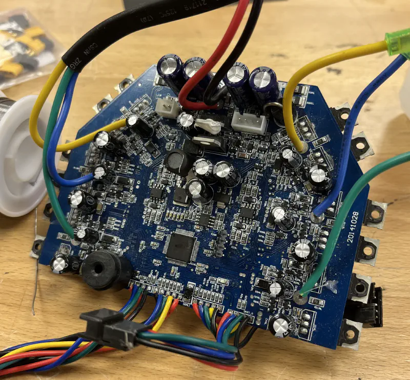
I used the ESC that came with the hoverboard parts as it was already rated for the motors, was a dual ESC on a relatively compact footprint, had voltage detection and current sensing for both motors and had ample I/O to interface with. I discovered the bipropellant firmware and planned to flash it to the ESC so I could tune my control parameters. I planned to also use the stock firmware that came on the sideboards to feed IMU data to the ESC.
I replaced the phase wire connectors on the motor and ESC to use MR-30 3-pin connectors to simplify the connection. I also redid the Hall sensor wires on the ESC with 22 gauge ribbon cable to further simplify wiring.
Footpads
The footpads are constructed from a material called Velostat. This material is a thick black paper that changes its conductivity through the paper as pressure is applied. I constructed the pads according to this video:
I was forced to use digitalRead for the footpads (see software) which proved challenging. Since the footpads only produced an effective resistance from ~250 ohms to 0 ohms, the voltage did not map properly to the trigger voltage on the GD32 pins. A simple voltage divider with the footpad as R1 and a 220-ohm resistor on R2 produced an adequate signal for foot detection. This wasn’t perfect, sometimes the pad would not deactivate due to a long ride and the footpad layers still smashed together. This only occurred when you tried to heel-lift (the recommended way to get off an Onewheel) and just jumping off the board with two feet was enough to deactivate.
There were some funny errors while getting this behavior working. My favorite was jumping off the board, the footpad not deactivating (caused by a weak pull-down resistor), and the board rolling out of the shop I was in. It went right out the open front door and went flying across the parking lot at 10mph until I caught up to it and turned it off. The only cracks on the electronics compartments are from that incident (it hit a concrete pole while escaping) and with a bit of epoxy, they have held up since.
Battery
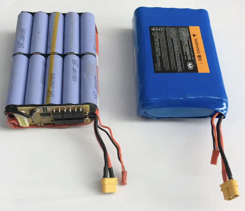
The battery that came with the original hoverboard was also an issue. Thedirits ended up using the battery but made a sacrifice in looks by having the battery hang out the bottom of the electronics carrier. Not only is this dangerous since the Li-ion cells are completely unprotected from any debris that gets kicked up by the wheel, but it’s not a clean solution. I opted to build a 10s2p battery out of 18650 cells. I purchased 22 Samsung 22P cells for $0.85 each from BatteryHookup. BatteryHookup does not appear to have the cells anymore (they seem to be a battery auctioning site), but you can usually find them for about $1-1.50.
I, unfortunately, do not have any pictures of me building the cell because I was too focused on not shorting the cells out and setting the local maker space on fire. However, I followed a process very similar to this video from Spire Engineering.
I was concerned about charging the battery. I fly RC airplanes and drones and it is crucial that you charge a multi-cell battery with balancing. I did not want to have to plug in a balance charger each time I wanted to charge the board. I wanted one cable that I plugged in and everything was handled for me. Fortunately, 42v chargers are extremely cheap on Amazon (~$15) and include a neat little charge indicator on the brick. They do not do any balance charging though. Enter the Inductive Balance Board.
This little board plugs into the balance lead on the battery and uses the voltage from surrounding cells to keep all cells evenly charged and prevent the possibility of overcharging. This balancing technology was noticeably absent in many early hoverboards, leading to the fires that made headlines. I could have used a BMS for the battery. A BMS essentially contains a cell balancer, under-voltage cutoff circuitry, and thermal protection. I already had under-voltage detection on the ESC and thermal protection was only provided by some of the more expensive BMS boards. That left only the cell balancer that was missing which the inductive balance board took care of.
This left only a 42v charger that was normally used with hoverboards and the inductive balancer to handle charging.
Lights
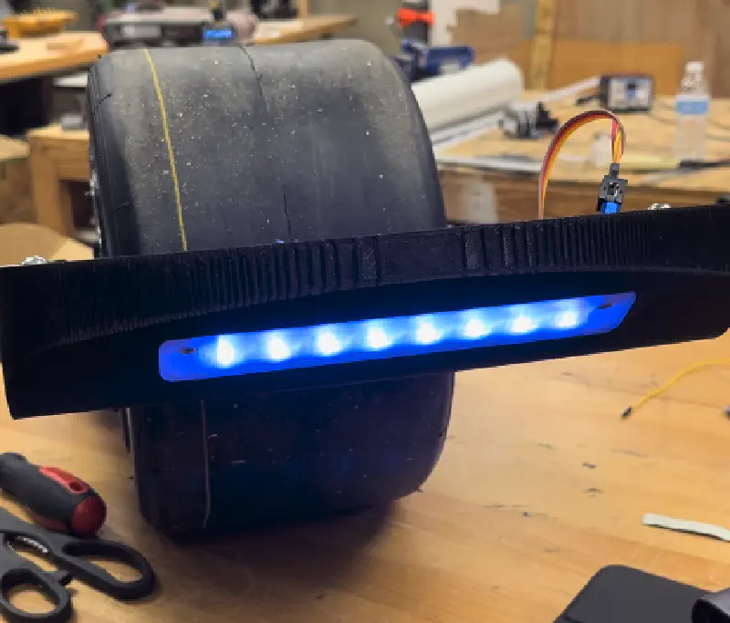
I knew there was a chance that I would be riding the board at night and wanted some form of light on the board. Unfortunately, I only thought of this after I had printed the battery mount and lights were only added to the front. I had a small strip of WS2812B addressable LEDs that I added to the front with a small 3D-printed diffuser. It made for some cool lighting effects and did a decent job, when turned up to 100%, lighting up the ground in front of me. I still carry a flashlight when I ride at night since it is not as bright as I would like it to be. These were powered off of the 5V regulator and controlled by the sideboard.
Software
The stock sideboard firmware and bipropellant ended up not working. There is so much variation between vendors that bipropellant is unable to support every hardware combination. For whatever reason, I could not get the sideboards to communicate with the ESC to send IMU data from the onboard MPU6050 sensor. Every combination of word length and baud rate failed to work.
Fortunately, the chip on the sideboards is an STM32 that has the programming pins broken out to a convenient header. I connected an ST-Link, unlocked the flash, and was able to upload Arduino code to the board. I used the electroniccats/mpu6050 library and standard Serial library to output raw MPU data through the existing connector. I originally planned to just send raw angles to the ESC and do all control calculations on the ESC. While this would be the most optimal way to do this, the bipropellant firmware is very complex and implementing a new communication protocol would have been time-consuming.
I instead opted to use the existing UART communication protocol that bipropellant includes. I was able to send motor commands over UART as well as retrieve telemetry back from the ESC (battery voltage, motor speed, motor current, etc). Instead of running all of the balance calculations on the ESC, I would do all calculations on the sideboard’s STM32 and only send motor commands to the ESC. This made it much easier to build the complex behavior of an Onewheel’s control system in a loop that I controlled and could easily debug outside of the complex ESC firmware. This was still by far from perfect for making small tweaks to the control settings. Any time I wanted to adjust a control parameter, I had to unscrew the footpad, disconnect the pressure sensor, connect the ST-Link, upload the new code, disconnect, connect the footpad, and screw down the footpad. This is one of the biggest changes that I planned for V2.
The control loop was able to run at 500hz comfortably, with loop times around 1500uS (2000uS is max for 500hz). This did not sacrifice any performance, and testing showed rates of ~400hz were sufficient for smooth control. This was with all Serial, LED, and footpad readings in a synchronous loop. I did not utilize any RTOS features like tasks to try to increase performance.
The sideboard had a GD32-type microcontroller (a pin-compatible alternative sometimes used in place of the real STM32). I attempted to use the Gigadevice core for the Arduino framework but found that there was incompatibility with the chip on the sideboard. Surprisingly, the STMduino core worked fine for the GD32 on the sideboard. However, there was some weird I/O incompatibility that made analogRead non-functional. Thus only digitalRead could be used to read the footpads.
Control Algorithm
I won’t delve too much into the control algorithm and all of the small edge cases and tweaks I applied. All of the code can be found here for you to peruse.
The control loop uses a PID-inspired design. My P-term is the angle of the board relative to the angle set-point. I do not have any I-term, the usage of this term makes the board essentially un-rideable as the board will accelerate infinitely if you are leaning forward. For my D-term, I do not take the rate of error from the set point. Instead, I use the angular rate term (in deg/s) directly from the IMU. This is what VESC does for their balance app and it eliminates any weird outputs when the set-point is changing.
For pushback, I have a timer that starts any time the motor duty cycle is commanded above 85%. It resets the timer when the duty cycle drops below. If the timer reaches 500ms, it initiates pushback which sets the set-point to 2 degrees of up-tilt. This commands the motor to essentially 100% and makes it feel like the board is tilting back and forces the rider to slow down. This is similar to the real pushback on an Onewheel.
Finally, for starting the board, I activate the motor control loop about 5 degrees from level and that allows the board to settle itself and help the user up onto the board.
There are a bunch of cross-fading these values and other small behaviors that are described in the code if you would like to know more about the control theory.
I have not pushed the motor duty cycle cap past 600 as some users have reported odd behavior above that point. In theory, I should be able to reach 10-13mph with the hardware I have, I am currently sitting at about 8mph. I am planning on switching away from the bipropellant firmware as it is no longer maintained and the Serial telemetry from the ESC is broken and hasn’t been fixed in over a year. The EFeru FOC Firmware is actively maintained and the Docs are amazing. It should be as simple as reflashing the ESC and replacing the ESC sending commands.
Results
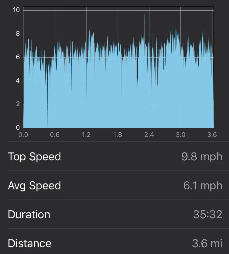
The board rides at about 8 mph comfortably. There are ways to increase this speed which will be in V2. I am by no means an experienced Onewheel rider and I haven’t pushed the limits of this board. It is perfect for me to go to class with and carry with me. The weight sits between a PintX and an XR. It is just a bit larger than a PintX while having the size of an XR wheel. I am unsure about the total range on a charge but calculations estimate about 5 miles. The picture above only shows 3.6 but the campus got too dark so I ended early.
Here is a short video of me riding the board for the first time. Needless to say, I need a bit more practice on it before I can start going faster!
This entire project’s code has been open-sourced on GitHub. I will eventually open source all of the CAD for the board, along with the files to 3D print everything. I am still working on a ton of improvements to bring it closer to a final project. I am working on V2 next semester and will bring a ton of quality-of-life improvements to it!